|
I
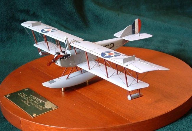
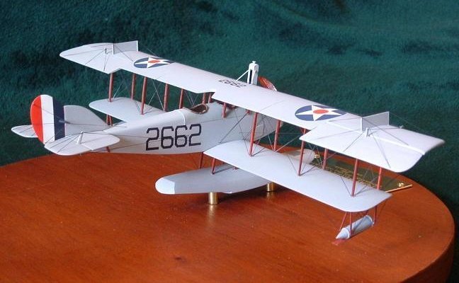
am a big fan of Pre World War 2 US Navy aviation, and one of my favorite
aircraft has always been the Curtiss Jenny. Having grown up in Upstate New York,
not far from where Glen Curtiss developed his designs and grew his company, also
helped foster that interest. When I read the original article in the July 1993
Fine Scale Modeler, of how Carl Park built his N9H, using three Lindberg Jenny
kits, I knew I had to do it. I did do some minor differences from his article,
in that I used only 2 Jenny kits and a Lindberg SE5 kit to pirate the Hispano
Suiza engine from. The only real reason he used 3 Jenny kits was to have an
extra Stabilizer to cut the Ailerons from. I choose to scratchbuild these
instead. With his article in hand, a set of drawings obtained from the Naval
Aviation Museum in Pensacola, and photographs I took of the N9H on display
there, I began cutting plastic. In the paragraphs below, I have outlined some of
the techniques I used and work involved.
Fuselage
One
kit’s fuselage was used as the actual model, and the other was cut up to use
as masters to vacuform new coaming over the Cockpit, and a reshaped Turtle Deck
behind the Cockpit area. The kit interior walls were thinned considerably, by
scraping with a cabinet scrapper to approx. half the original thickness, for a
more scale like appearance. Interior Longerons and structure was added, along
with internal bracing wires. Control yokes, unique to the N9H were made from
brass wire soldered together, with control wheels from a spare PE Fret. The
Floor was made from 1/64th plywood, as was the forward bulkhead and
Instructors Bulkhead. Rudder bars are fashioned from basswood strips, with
Rudder Fairleads attached as appropriate. The seats are made from .010 plastic
sheet with tape belts and PE Buckles. The Cockpit is accurate, with only the
Instructors rear Cockpit having any flight instruments. Students literally
learned to fly by the seat of their pants. The are of the cowl was heavily
reshaped as the N9H has a much different cowl, forward area, and side panels
than the Jenny. A New Nose was vacuformed and installed, as well as a corrected
Hispano-Suiza Engine from a Lindberg SE5 kit. The engine was detailed with both
Magnetos, full ignition wiring, plumbing underneath for cooling lines (even
though you can’t see it, it’s there) scratchbuilt Intake Manifold and Carb,
and Exhaust pipes. The prop is from Copper State Models, with brass foil applied
for the lead edge protectors. All Cabane and Wing Struts are heavily modified
kit struts, jigged for accurate placement. The Radiator is scratchbuilt using
Evergreen Plastic Channel, Rod and Strip, and brass screen. Control Lines were
rigged using Lycra Thread.
|
Click on
images below to see larger images
|
 |
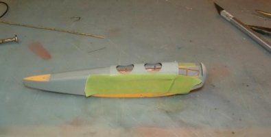 |
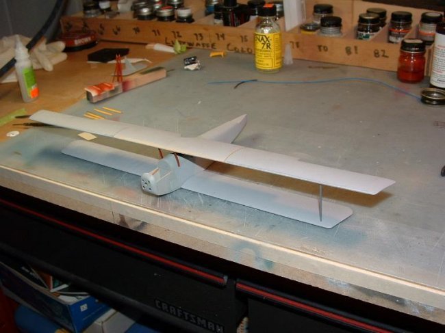
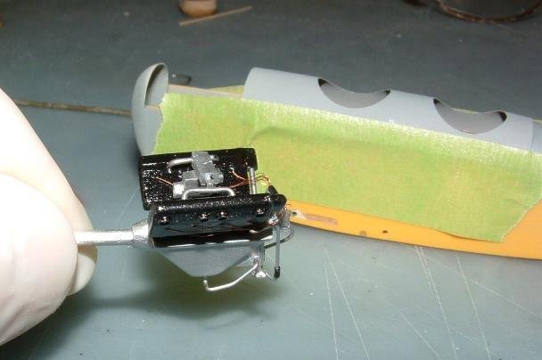
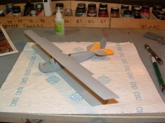
| Fuselage
under construction. Engine is being test fitted in this picture. Note
the different colors of plastic wings from the two kits used. Interior
structure is stained basswood |
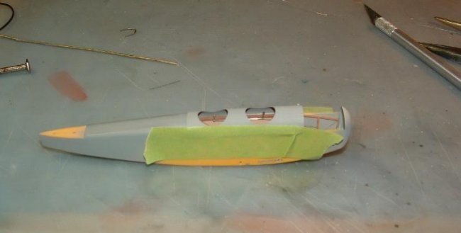
Fuselage
under construction.
Vacuformed Cockpit cover and rear Turtle Deck have been fitted,
and interior components have been installed. New Nose has been
|
Wings.
This
is where most of the work was done. N9H Wings are 10 feet longer in span than
Jenny wings, so 2, 3-1/2 foot stubs were added to the lower wings, and a 10 foot
center section was added to the Top Wing. Wings from both kits were sectioned
and glued together. All rib detail was sanded off as it was too intense, giving
a “starved cow” look to the wings. Actual fabric wings are drum taught, not
sagging like many kits portray it as. After the wings were sanded smooth,
individual decal strips were laid on using pencil guides where rib locations
were. The wings were squared up in a jig, then strut attachment holes were
drilled, as well as rigging attachment points. The gaps in the Upper wing are
accurate. There was a 2-inch gap between the panels on the actual aircraft. The
rigging was done using Lycra Thread, stretched from locating hole to locating
hole and seized with a drop of CA. All Rigging is accurate and functional, due
to the length of the wings I didn’t want them sagging. The real aircraft used
doubled Flying wires, and single Landing wires. Ailerons were fashioned from
.005 sheet plastic with a .030 lead edge rod, embossed from underneath for rib
detail. The Skid fences on the Upper Wing are also made from .010 plastic and
.020 Rod. Pulleys for the Ailerons were punched from .030 plastic using a
homemade punch, and held in place by fine wire brackets as the original. A jig
just for this model was made to hold everything in alignment as each strut was
cut to fit and glued in place. Wing Bay Bracing Wires were set into the strut
holes before the strut was glued in place.
|
Click on
images below to see larger images
|
 |
 |
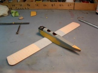
| Wings
fitted and a dust coat of primer sprayed on wings before sanding off the
overly done ribs. |
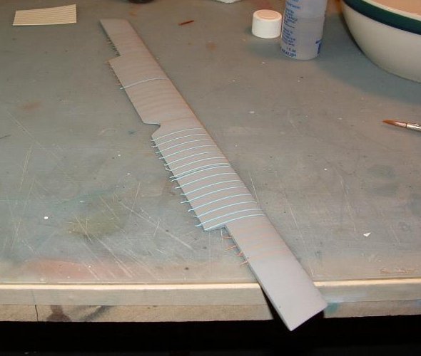
Tedium
on display. Individual strips of decal strips being laid on the wings,
following pencil marks indicating Rib Stations. These were then
oversprayed with Primer again, then painted. |
|
Click on
images below to see larger images
|
 |
 |
|
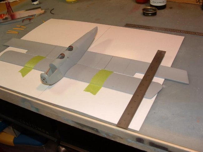
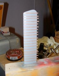
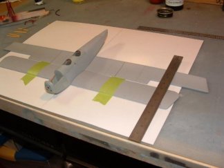
Upper
Wing being taped. That sucker is almost 13 inches long. The N9H was
somewhat underpowered, and needed a longer span to generate enough
lift to break free of the water suction on the bottom of the float
|
First
trial fit of the upper wing to the Cabane Struts. |
Tail
Surfaces.
The
Fin on the N9H is “humpier” in profile, so a new Fin was made using .030
sheet. Kit Rudder was used, after sanding down trail edges and fixing outline of
Rudder. Kit Stabilizers and Elevators were used, with the same sanding of trail
edges. Control Horns are made from .020 plastic to replace the overly thick kit
items.
|
Click on
images below to see larger images
|
 |
 |
|
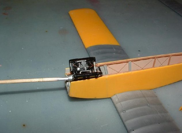
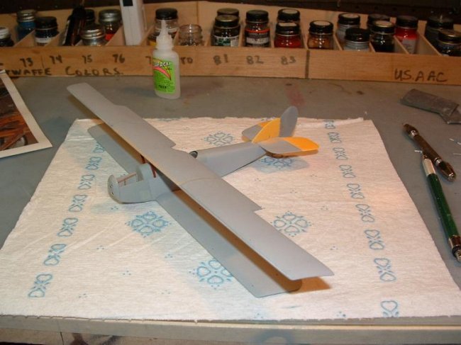
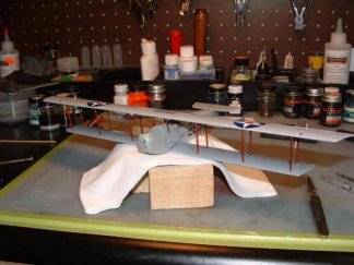
All
major airframe work has been done at this point. It’s starting to
look like an airplane. Note the new Fin, cut from the left over
kit’s Stabilizer.
|
Major
Blonde Moment during construction. When laying out the strut location
holes I used tape to hold model firm to layout sheet. Guess what else
came off when I pulled the tape up? Yep… you guessed it. 4 rib tapes
per wing. Duh. |
|
Click on
images below to see larger images
|
 |
 |
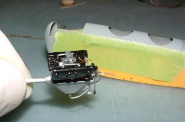
| The
completed Engine. Scratchbuilt Intake and Carb, all coolant and oil
lines present. |
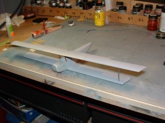
The
Model after removing the jig fixture. Struts have been installed and
Rigging is starting. |
Floats.
Main
Center Float was carved from Basswood, sealed, sanded and painted, then holes
located and drilled for Strut attachment. Rigging wire points were also drilled.
Wing Tip Floats are turned ¼ inch dowel, with .005 strip wrapped around for
joint lines. Struts for floats were made from .020 plastic, sanded to correct
shape and profile, with brass pins in the end for mounting strength. 1200 grit
wet/dry sandpaper makes nice anti-skid areas, and brass wire was formed and
soldered together for the cleat on the Main Float.
|
Click on
images below to see larger images
|
 |
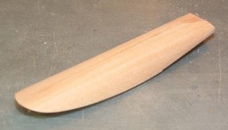 |
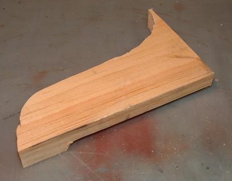
| Inside
this scrap basswood there is a Main Float…. |
See?
There it is, after about an hour’s worth of carving and sanding. ( and
3 beers for steady nerves)4 |
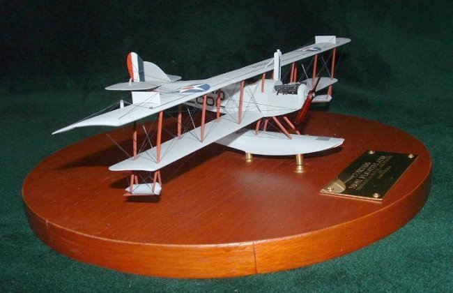
Paint/Decals
Paint
is Duplicolor Sandable Primer. It’s as close to Navy Gray for that era as you
will find, and being lacquer based sprays easily. After painting the model was
sealed with Future prior to using various decals from the scrap box to represent
one of hundreds of N9H’s delivered to the Navy. A final overcoat of Dullcoat
to scale down the gloss and the model was finished.
Base
The
base is ½” Particle Board with Mahogany Veneer, stained and sealed, with
Brass Rod used to attach model to base.
Mike
|
|