| Aftermarket
items: Black Box F-100D Cockpit Resin Set |
|
Paint used:
Gunze, Model Master and Alclad II
|
|
Decals:
Monogram stock and Superscale
|
KIT
REVIEW
Monogram
currently stands alone in the market when it comes to an F-100D in 48th
scale. ESCI had an
F-100 in 48th scale but apparently it was not as good as the Monogram
offering, and I believe it is out of production.
This Monogram kit dates back to the 1970s along with rest of their
Century Series models. There
have been several releases of this model. This
incarnation of the Monogram F-100D is a kit that was released around 1995.
Typical with any classic Monogram kits, it has raised panel lines and a
detailed cockpit. As with any released classic Monogram kits it has poor
fit up. I am informed that this has
something to do with an aging mold. I
have seen some original released Monogram kit and I can honestly say they fit
mostly darn well. But despite
the shortcoming of the poor fit, this kit builds into a really nice and accurate
model of an F-100D.
The parts are
molded in the form of silver colored styrene and the plastic has just the right
stiffness and hardness. The
later reincarnation of this kit is molded in grey styrene and the plastic is
very soft. The molding is clean overall with very little flash to clean
up. There are no photoetch
parts in this release as it is not one of those Monogram “Hi-Tech” series
kit.
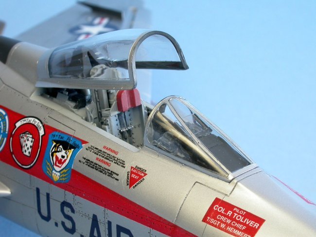
The cockpit and
the seat are highly detailed for stock parts.
The seat is a three part seat that comes with molded in cushions
and seat belts. Although
nicely detailed, the seat could be improved when judged by 21st
Century standards. A Black Box
resin cockpit is a good investment, however, it is not a must have item. A good compromise would be to use the stock cockpit and use a
resin seat from Legend (Korea) to kick it up another notch.
Since I have AMS (Advance Modeler Syndrome), I bought and used the Black
Box resin cockpit set.
Fit
Up and Construction:
Dry fitting was
performed on the parts prior to assembly to assess the challenge that was to
come. The fuselage halves
joint is a horizontal type joint that is about quarter of the way up from the
bottom of the fuselage. This joint
is not perfect but do-able if a lot of liquid cement is used to melt the
plastic. The tail
cone and the nose intake came as separate pieces.
Two choices of early (F-102 nozzle) or late model exhaust cones are
provided. The instruction provides
good directions as to which cone to use.
These parts do not fit well to my model’s fuselage.
Some shimming and serious sanding was required here.
The stablizer
was molded with the upper fuselage halve.
This will make sanding of the fuselage joints very difficult and messy.
This also will not allow me to pose the stablizers in the down position
that I see that many parked F-100 have. To facilitate matter, I carefully cut
off the stablizer with a sharp No. 11 blade and saved them for later use.
The entire
upper wings are molded as one piece with a middle tab that connects both wings
together. This will make wing
alignment a breeze. However, a gap
is noted between the wing root and the fuselage.
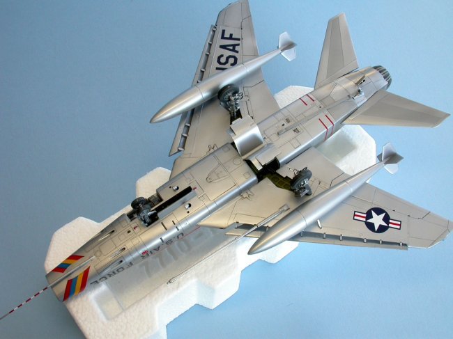
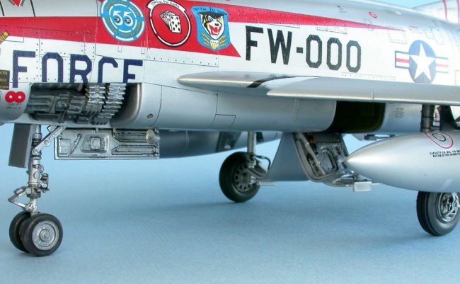
As a bonus, the
port side ammunition bay and gun bay are molded on the fuselage.
External panels for these bays are also provided if you do not want to
show these as open bays. Typical
with most Monogram kits these panels go on with very noticeable gaps.
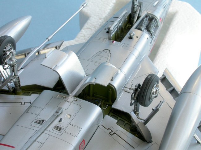
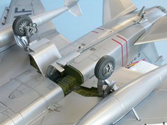
The main gear
bay, nose gear bay and landing gears has sufficient details and are nicely
molded. The main gear doors are
beautifully detailed and should be shown in the down position to show off the
details.
Construction:
|
Scribing Panel Lines
I start
the building process by wet sanding off most of the raised panel lines
from the wings and fuselage. One advantage of silver colored molding is that even if you
completely sanded off the raised panel lines, you can still see a clear
dark impression of where the panel lines used to be. This is not so for other colored styrene.
As such, I rescribed the complete model along these previous panel
line locations while checking with my reference books.
|
Click on
image below to see larger image
|

|
|
I do not want
to show the ammunition bay at the side of the cockpit.
Typical with the Monogram kits, the panel does not fit well into the
opening thus resulting in a very noticeable gap as compared to my scribed panel
lines. Because I will be doing a painted silver and NMF
finish, I cannot have any putty joints for they will ruin the finish.
Hence, I glued the ammunition bay panel to the fuselage with copious
amount of liquid cement. The aim here is to melt the plastic surrounding the joint and
to let it ooze out to totally seal the seam with native plastic.
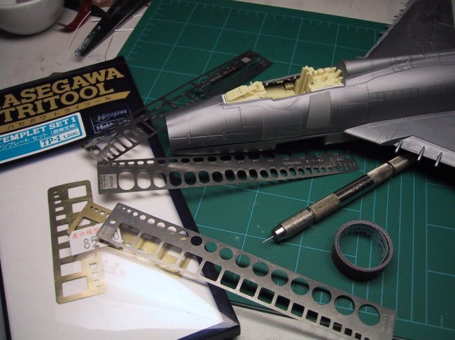
Once dried, I wet sanded smooth the joints down flush with the rest of
the fuselage. One of my rule
of thumb for scribing is never scribe directly over a glued joint whenever
possible. As such, I carefully
scribed out the ammunition bay panel lines just outside the glued joints
resulting in a clean scribed panel line. The scribing tools I used are shown on the photo along
with the completely rescribed fuselage.
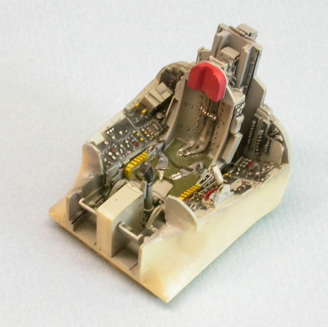
Black Box
Resin Cockpit
I start by
separating the resin parts from the pour stubs using a hand saw blade.
After studying the instructions and dry fitting, I determined that it
will be rather difficult and time consuming to thin out the kit cockpit side
walls to accept the resin side walls. The
best alternatives I figure is to scratch build the side wall details by using
the BB parts to model from.
The rear deck
and the front dash/instrument panel on the kit were cut out.
To ensure a tight fit, I oversized the cut out a bit on all sides and
then glued on a strip of 1/16” thick styrene strip with liquid cement.
While the strip is still softened by the liquid cement, I quickly
inserted the resin parts into the cut outs and pressed fit the parts together.
This resulted in a perfect snug fit without any further trimming or
sanding.
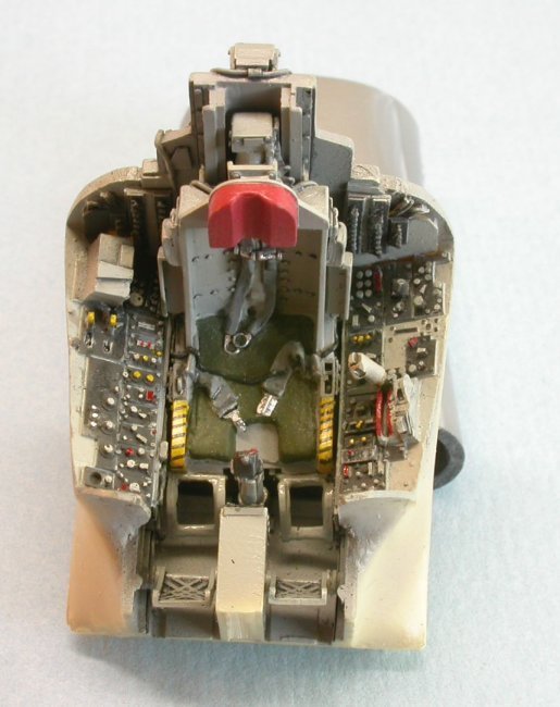
The BB resin
seat does not fit into the resin tub because of the raised details on the
starboard side of the tub wall. Consequently,
all the details there are shaved off to allow the seat to fit into the tub. Fit up of the leg restraints are poor and the
instruction does not help too much on this aspect.
All I can do was to keep trying until it looks right and the entire seat
assembly can fit into the tub. Other
than that the seat fit quite well and is an excellent representation of a seat
in an F-100D. The only criticism I
have is that the resin seat is designed too long (out of scale) and thus the
seat bangs right up against the control stick.
If this were real the pilot would not be able to pull up on the control
stick.
The tub, seat,
side walls, instrument panel, and rear deck were painted with Gunze Aircraft
Grey. After the based paint
was dried, all the parts were coated with a spray of Future floor wax in
preparation for an enamel wash for high lighting.
The BB tub has
most of the cockpit levers built in except for the landing gear lever on the
instrument panel. I added that by making it out of thin styrene sheet and glued
that onto the lower left side of the instrument panel.
Stablizer
I had
previously cut off the stablizer from the upper fuselage.
To enable them to go back onto the plane after painting, I cut a piece of
aluminum tube as a mount to fit inside the rear fuselage and glue that in the
same elevation as the original stablizer would go.
Another set of smaller diameter tubings were cut out and glued into a
hole which I drilled into each stablizer. This
arrangement will allow each stablizer to just fit into the mount and will allow
me to pose the stablizer in either up or down position.
|
Click on
images below to see larger images
|
 |
 |
Nose Air
Intake
The nose air
intake duct came as two halves. To
facilitate sanding of the seam I cut off the rear blanking.
This enables me to properly fill and sand the inside seam to come out
with a seamless intake duct. After
the sanding and paint, I replaced the blanking plate with a styrene piece which
was painted black. The kit
instruction tells you to glue the intake duct onto the upper fuselage halve
before gluing on the nose intake. During
dry fitting, I found that this will not ensure the best alignment of the nose
intake and the intake duct. Thus,
I glued them together first and then fit them to the assembled fuselage.
|
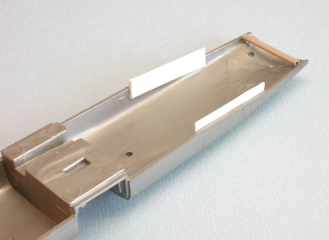
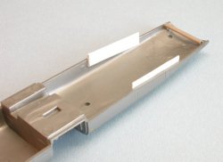
Fuselage
Assembly
To ensure
the best fit up possible, I cut off all the aft fuselage alignment pins.
To ensure the rear portion of the fuselage halves fit well and
won’t crack in the future, I glued an alignment / strengthening tab made
from styrene strips to the rear lower fuselage.
See photo for reference.
|
Click on
image below to see larger image
|
 |
|
The fuselage
halves were glued together without any fuss, although the joint was not a Tamiya
fit. I generously run liquid cement
along the joint until it was totally saturated with liquid cement.
This “melted” much of the plastic along the seam and allow me to
press fit the soften plastic together until the plastic oozes out and fill up
most of the gaps present. When this
dried, I wet sanded the seam with a home made sanding stick until the seam is as
flat and smooth as possible. At
this point I don’t care about sanding off any scribed details because I can
always rescribed them back later. Any
remaining gaps were filled with little bit of Tamiya putty and cyno glue.
The nose intake
and the tail exhaust cone were glued on with liquid cement.
These parts do not align too well to the fuselage and ended up with some
gaps. Some portions do not fit
flush with the rest of the fuselage.
A sanding stick was used to sand the parts flush with the fuselage. Quick drying cyno glue was used to fill some of the gaps.
Wing to
Fuselage Joint
The upper wings
were molded together with a connector piece joining the two wings.
This feature ensures the modeler can glue the wings on and get a perfect
wing alignment. Even though I had
studied the instructions many times, I totally forgotten that I was suppose to
glue the wings and the bottom landing lights on before I can glue the fuselage
halves together. This mistake turns
out to be serendipitous as you will see. I
separated the wings by making a single cut on the middle wing connector piece.
I shaved and sand the wing to fuselage joint such that each wing will go
onto the fuselage with a minimum amount of gap.
Note that I won’t be able to do this if I had followed the instruction
exactly. I glued the wings to the fuselage, all in the while manually
aligning the wings so that they sit perpendicular to the fuselage.
Doing it this way, I ended up with a wing to fuselage joint that is
almost perfect and not needing very much putty.
Landing
lights
As I mentioned
above, I was suppose to glue on the two clear lenses that represents the landing
lights into the lower fuselage half. But
I didn’t do that. This is solved
by posing the lights in a down position as shown on my reference book.
I made a set of landing lights from the left over spruce and attached set
of MV lenses. The landing light
hinges were made from bent brass wire. The
lights were attached as the very last step after painting.
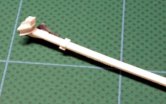
Arrestor
Hook
The kit
arrestor hook is awful looking. When
I first saw it, I couldn’t figure out what it was until I referred to the
instruction sheet. After
studying the reference books, I decided that I can make a better looking
arrestor hook than the kit supplied part. I
made a new arrestor hook by bending two pieces of styrene “C” channels and
glued them together. See photo.
It looks just like the real hook in my reference book.
|
Click on
images below to see larger images
|
 |
 |
|
Wing
Tanks and Pylons
The wing
tanks provided by the kit are the 275 Imp. Gal. tanks used by the early
F-100s. As every sources have
pointed out, the tanks provided by Monogram is short by 1/4”.
If you are totally into true scale then this will bother you a lot
and you will go out and buy a set of replacement resin wing tanks from
Aires. I felt the kit part is
more than adequate.
|
Click on
image below to see larger image
|
 |
|
The tanks from
the kit come in your standard two halves type of construction, with the pylon
molded to one halve of the tank. A
giant gap between the tank and the pylon results when the halves are glued
together. Thus, I cut off the pylon
from the tank and glue this back to the tank after the tanks are all assembled
and sanded smooth.
All the under
wing pylons do not fit well to the wing. This
is easily resolved by trimming and sanding each pylons until they fit well to
the wing’s curvature. It is
tedious work but it has to be done. Being
lazy and already into the 5th month of building this thing, I decided
to only put on the wing tanks.
Refueling
Probe and Pitot Boom
The refueling
probe and pitot boom on this plane are very long and slender.
If I just used the kit supplied parts, I know I will break them on my
first transport. Learning
from my past lessons, I rebuilt these parts from small diameter aluminum tubing
while using the kit parts as guide.
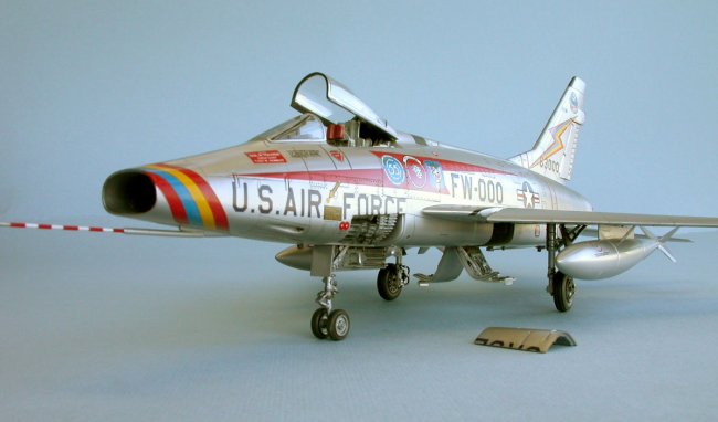
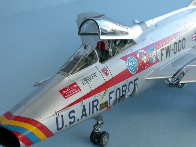
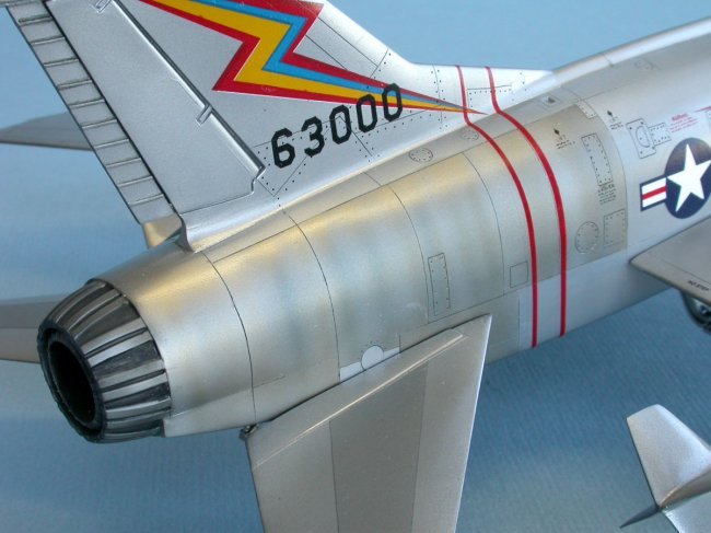
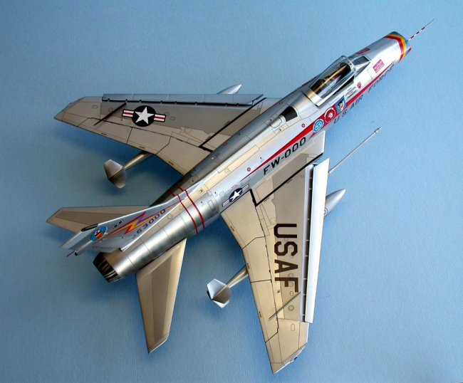
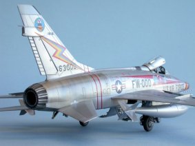
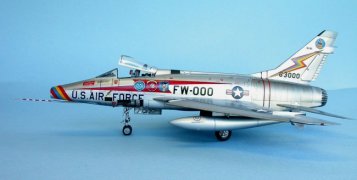
Color Scheme
Before I built
this model, I know I wanted to build one of most famous and best dressed F-100;
The Triple Zilch from the 20th TFW based in England in the late 50s.
This aircraft was flown by a senior Officer of the wing and its marking
carried the colors and unit badges of the three Fighter Squadrons.
I had studied
all the reference pictures I can find of the Triple Zilch and similar F-100s in
the late 1950 to early 1960 era and decided that the Triple Zilch had to have
been a plane that was painted with silver lacquer and not an all natural metal
finish. Thanks to Mr. Roger
Jackson’s advice, coupled with other reference material, I concluded that this
would have been true.
Painting:
For any NMF or
silver painted model, there cannot be any scratches or any basic finish
imperfections present. Any imperfections will unquestionably show up after you put
on the silver paint. Thus, a
silver or NMF model is a true test of a modeler’s skill in basic finish
techniques.
The model was
wet sanded with very fine (2000 grade) wet sanding paper.
This is followed by more wet sanding with even finer grade sand paper.
A light test coat of silver paint was quickly sprayed onto the model to
check for seams and scratches. When
scratches showed up, I removed the paint and sand again.
This process was repeated about 5 to 6 times until I have had enough.
By this time all noticeable scratches have disappeared except for some
really fine scratches remained. I
am not a perfectionist kind of person so I was OK with some of those tiny
scratches that you can hardly see. The
tail section of the fuselage which has natural metal finish was masked off with
tape.
To model a
painted lacquer finish, I sprayed the Model Master’s Chrome Silver paint
thinned with 30% thinner. If the
Model Master Chrome Silver paint is sprayed on thick and not thinned properly,
the paint will not dry well and will attract finger prints.
Hence, I made sure I put on two thin coats to cover.
I let each coat dried for one day before handling.
Everything went well and the paint did not attract any finger prints.
At this point the model looked great with its smooth shiny silver paint.
|
Click on
images below to see larger images
|
 |
 |
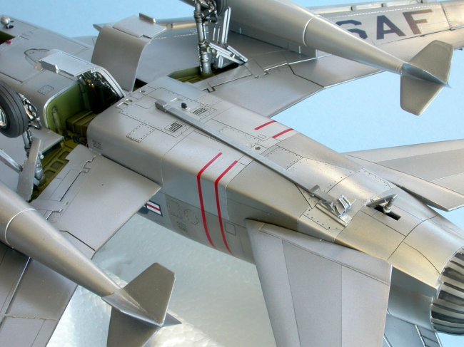
Next, I
sprayed on a thin coat of Future to seal the Chrome Silver paint and to dull the
sliver paint so it will look like a silver lacquer finish.
After drying for one hour, I masked off the areas on the upper wing and
stabilizer where a darker shade of silver has to go.
I used the low tack drafting tape here.
Even though the tape is low tack, much care must be exercised when
peeling the tape off of any silver paint. The
darker shade of silver was painted using the Model Master Metalizer Stainless
Steel paint.
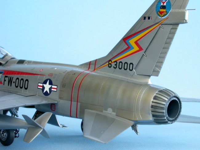
Next comes the
hard part of recreating the burnt metal look of the rear portion of the fuselage
where the natural metal was heated by the engine heat.
The reference books showed the Triple Zilch and other F-100s in the 50s
were kept really clean and well maintained.
The rear natural metal panels were kept well buffed and polished.
Hence, only some light burned effect has to be modeled.
To do this, I masked off sections of the rear panels and painted it with
Model Master buffinge Aluminum Plate Metalizer paint.
After drying for 10 minutes, I buffed this up good and shiny.
Then, I set my Paasche VL air brush to fine spray the Alclad’s Pale
Burnt Metal in a series of vertical lines along these panels while leaving a gap
between each lines. Some selected
places, I double sprayed to achieve darker shading as shown by my reference
materials. I can’t say enough
about how well it is to spray the Alclad paint as it sprays on extremely well
without having to play with the airbrush to get a fine line.
To even accentuate some darker burning of the metal on the middle panels,
I spray on lines of thinned out mixture of Gunze clear blue.
|
Click on
images below to see larger images
|
 |
 |
The above
technique resulted, in my humble opinion, with a realistic rendition of the
burnt metal panels on well kept F-100s. Now
if I were to model a Nam era F-100s, I would go heavy with Alclad Pale Burnt
Metal paint and with repeated heavy application of the Gunze clear blue.
I would even repeat by going over the burnt metal lines with a thinned
out mixture of red paint applied in light fine lines on selected locations just
to get in some random effect.
The entire
model was again coated with a coat of Future to seal everything in preparation
for decaling and a light dark grey wash for panel accentuation.
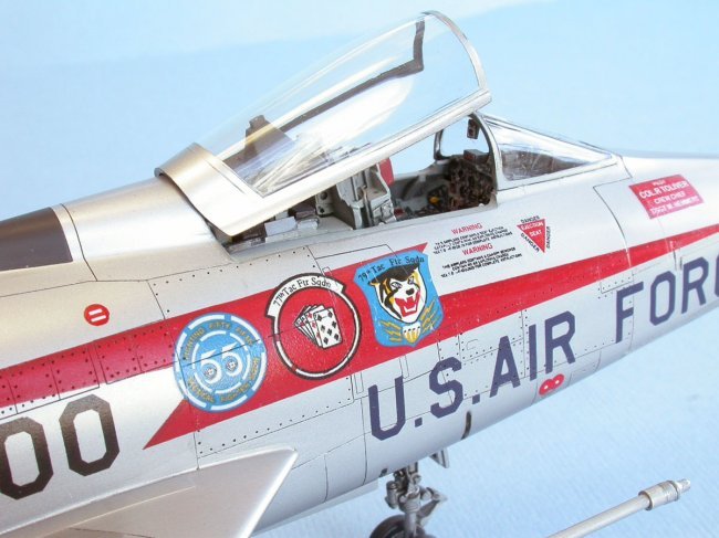
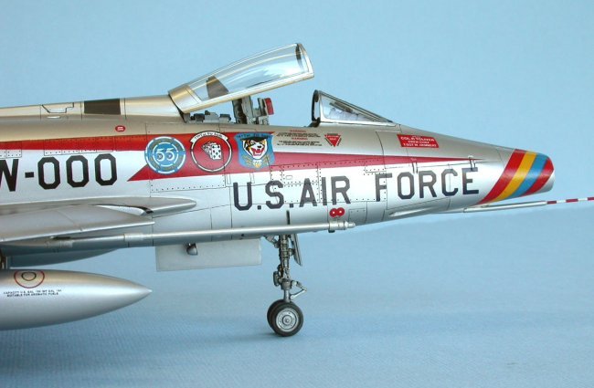
Decals:
Currently,
there is no after market decals in 48th scale for the famous F-100
Serial No. 56-3000, nicknamed “Triple Zilch”.
Superscale used to sell a sheet (sheet No. 48-80) with the Triple Zilch
marking but is apparently not available at this time.
The other source is Monogram which issued a stock decal sheet with the
marking of this well dressed aircraft.
Lucky for me, Uncle Rick of Uncle Bills Hobby Shop had one sheet and he
generously gave me his.
|
Click on
images below to see larger images
|
 |
 |
The quality of
the decal sheet is a little better than the typical Monogram stock.
It is fairly thin but some markings are off register with some white
showing on the outside edges. This
required that most of the markings must be trimmed with a sharp No. 11 blade to
get rid of the extra carrier film. The nose band and the tail lighting bolts
have bubble texture, can’t do anything about that.
I am just thankful that I can get hold of the decal sheet. When I wet the decal for release, some white “stuff”
under each decal shows up, especially evident on text type decal with clear
carrier film. I am sure this must
the glue but I can’t risk keeping it on in case it does not dry clear.
The Monogram decal set in nicely with Gunze’s Mr. Mark Softer decal
softener. This solution is a strong
solution and works well with most decals. However,
it reacted a bit with the Future and when dried, it left some white stain on the
surfaces around the decals. My
worry was quickly dispelled when I applied a coat of Future over the completely
decaled model and the stain disappeared completely.
The standard
markings such as “USAF”, the national insignia, “US AIR FORCE”, and most
of the stenciling came from a Superscale decal sheet for the F-100.
The decals from Superscale are very thin and go on well with Micro Sol.
However, most of the stenciling texts were printed off center from the
carrier film. As a result, top
portions of some texts disappeared when the decal was released from the backing
paper.
Final
Remark:
After putting
in about 5 months of on again/off again work on this kit, and putting up the
challenges of painting, and decaling this thing, I am very satisfy with the end
result. Even my wife likes this
model because it is very colorful and she likes the burnt metal look of the rear
fuselage.
It is NOT an
easy model to build for the level that I was trying for, and I did not achieve a
perfect model. However, I do have in my small collection, a good rendition
of my favorite F-100D. It was a
good challenge. Oh yea, I’m happy.
References:
- Detail
& Scale Vol. 33, F-100
Super Sabre by Bert Kinzey
- Detail
& Scale Vol. 14, Part 1, Color
and Markings of the F-100 Super Sabre by David W. Menard
- f-100.org,
web site dedicated to the F-100, http://www.cybermodeler.com/f-100/hun.shtml
Wayne
|