|
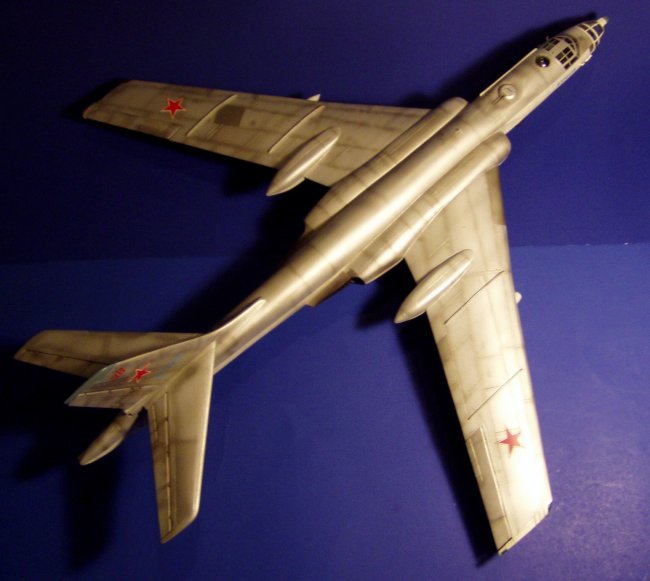
When Trumpeter released the ‘Badger’ in 1/72, I was shocked. For years
the ‘Badger’ and the ‘Bear’ represented the ‘Red Threat’ during the
cold war, often shadowing NATO task forces at sea. Finally, we had a good
kit in my favorite scale.
Although originally designed as a missile platform and bomber, many Badgers were
converted later in life into reconnaissance platforms and for other missions.
In fact, the Tu-16 enjoyed a second lease on life due to its useful payload and
range once it was supplanted by the Tu-22 ‘Blinder’ and Tu-22M
‘Backfire.’ Trumpeter’s releases represent the Badger-C and Badger-G
bomber/missile carriers. I wanted to build one of the later, converted,
variants with exotic bulges and scabbed-on equipment. For this conversion,
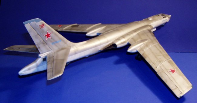
I chose to make the Tu-16RR NBC Reconnaissance variant. The Tu-16RR was
equipped with two teardrop ESM fairings under the fuselage, a thimble nose ECM
antenna, and a large ECM fairing scabbed onto the tail replacing the tail guns.
Additionally, there were pylons with NBC sampling pods under the wings, and some
smaller electronic antennae at the air intakes and the nose.
After thoroughly inspecting the kit and dry fitting, there were several items
with the kit that needed improvement beyond those already identified for a
conversion. I was dissatisfied with the air intakes and exhaust detail.
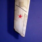
The port wing needed to be modified to represent a Russian Badger with its
unique wingtip in air refueling system. The main gear were set too far
aft, and the door configuration was incorrect for a Badger on the ground.
The nose glazing was incorrect (it should be asymmetrical). Finally, I was
not happy with the kit’s thick, distorted clear parts—so those would need to
be vacuum formed. Fortunately, overall I was very pleased with the general
fit and detail of the kit. The thick, sturdy plastic of the kit was sure
to make a good strong product despite the size of the aircraft.
Click on
images below to see larger images
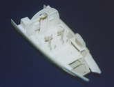
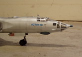
Work started with the crew compartments and the forward gear bay. The gear
bay was detailed with styrene strip, rod, and tubing. Detail was added to
the forward landing gear. The gear and bay were painted neutral grey.
The cockpit was largely scratchbuilt, including the seats. Ribbing was
added using styrene strip. The navigator and bombardier’s compartments
also received a heavy dose of scratchbuilding. A bomb sight was stolen
from a B-29. Reference photos show the interior of the lower forward
navigator’s glazing obscured by metal. I added this with 0.020”
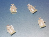
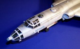
styrene cut to shape. Similar detailing was performed in the tail and
waist gun locations. The remote gun aiming equipment—visible from the
waste blisters and the dorsal bubble behind the cockpit—was stolen from the
B-29 also. The tail gunner’s compartment was detailed with ‘black
boxes’ for the ECM tail. The interior was painted zinc chromate green,
with black and grey electronic boxes.
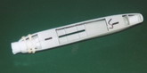
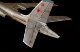
For the ECM tail, I cut away the tail gun mount to just aft of the gunner’s
side windows. I covered the cut with 0.040” styrene which was then
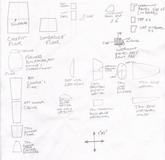
trimmed to form a bulkhead. I designed the new tail as a transition piece
and the actual ECM cone. I then created a ‘skeleton’ of the top and
side profile for the transition and cone (see drawings). These pieces were glued
to the cone bulkhead. I crudely filled this skeleton with Milliput.
When the Milliput dried, I carved and sanded it to the proper shape for the tail
fairing. Then, panel lines were scriped into the final piece. To
compensate for the significant weight of the tail addition, I added excess
weight to the nose in order to avoid a ‘tail-sitter’. ECM/ESM blisters
for the ventral fuselage were made similarly, although I used just a
cross-sectional piece of 0.040” styrene to establish the proper shape, then
filled with Milliput.
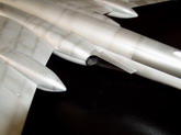
Next, I tackled the intakes and exhausts. Unfortunately, at the time [I
built this kit in 2002] I lacked sufficient references, so I placed the
compressor face about 30mm from the intake entry. In reality, the intake
trunk splits, carrying air above and below the wing spar to the engine which is
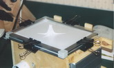
buried much further aft in the cowling. For the intakes, I made a Milliput
master, forming the entry at the lip of the intake and then smoothing it to the
proper diameter for the compressor face about 30mm from the lip. I then
vacuum formed copies of this master. The compressor faces (stolen from the
spares box) were glued to the intake trunks. The exhausts were a little
easier. The turbine detail was stolen from a 1/72 B-52H. The
turbines were glued to styrene tube of the correct diameter. The tubing
was glued to the rear of the engine fairings leaving significant excess hanging
out of the back. With the engine fairings together, the intakes were
pushed in from the front, again leaving excess out the front. I used
liquid cement to bond the intake to the fairing. When the glue was dry,
the excess material was cut away, and the intakes and exhausts were sanded flush
to leave a smooth transition.
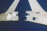
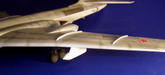
The wings and main gear bays were the next major assembly. The mounts for
the main gear were cut away and re-positioned. Detail was added to the
bays, although little would be visible with just the small gear doors open.
Some detail was also added to the gear. I drew an approximation of the top
view for the port wingtip onto 0.040” styrene and glued it to the wing tip
(see drawing). I then faired the addition with Milliput.
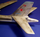
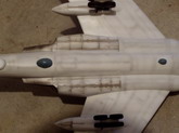
After major assembly, the model was painted with Tamiya white on the bottom and
Polly-S metallics on the upper surfaces. The starboard rear bombardier’s
window was added using Micro Crystal Clear. The pylons and sampling
equipment under the wings were modified from various spares in the spares box.
If you choose to use my drawings as a basis, note that they were originally to
scale. There is a reference cross-hair which was originally 1” x 1”.
You can use that to get the drawings back to their original dimensions.
This is a relatively easy conversion. I am disappointed with the error on
the air intakes, but the work was a good learning experience on intake
improvement. With the myriad of references and walk-arounds available
since I originally built this kit, you could easily build just about any of the
of numerous versions of the Badger.
Tom
Berres
Click on
images below to see larger images
|